

Home / Systems / Compound Wall
Compound Wall
System.
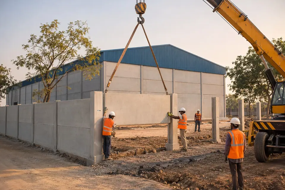
A finished boundary wall, gate to gate. Posts stand in socket footings and one panel closes each bay. No curing on site.
Indicative figures · Notes
02 · Elements
Four elements make the wall.
One panel per bay, so the wall reads as a clean concrete surface.
Explore the wall in 3D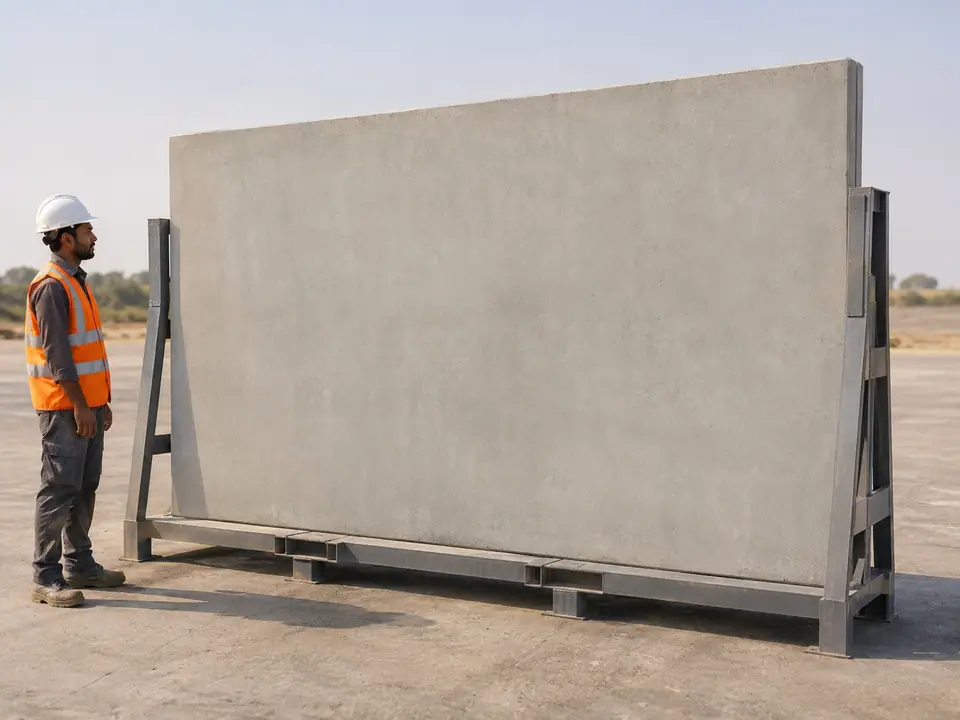
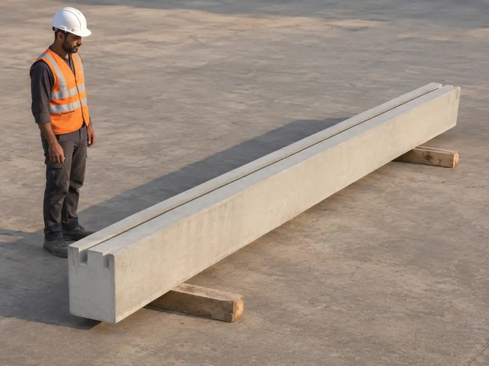
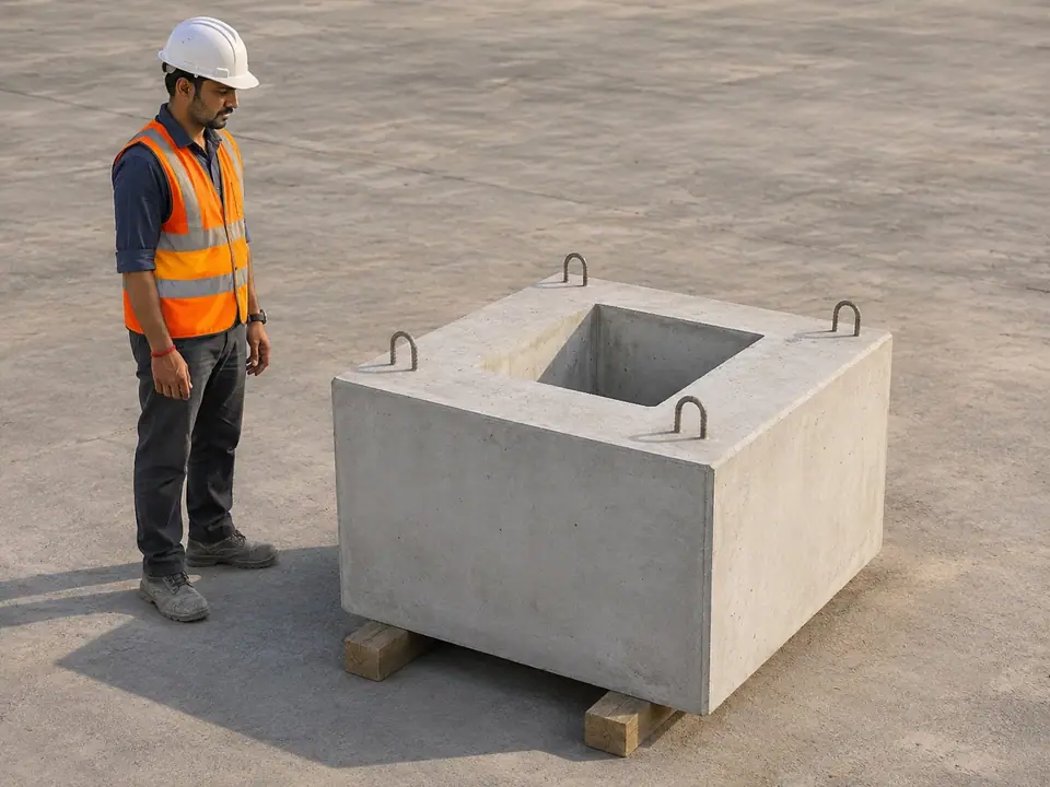
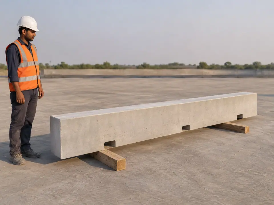 Illustrative renders
03 · Sequence
How it is installed.
- 1
Set out
The wall line and post positions are marked.
- 2
Footings
Socket footings are placed in excavated pits.
- 3
Posts
Posts are lowered into the sockets and grouted.
- 4
Panels
One panel is lowered into the slots of each bay.
04 · Scope
What you get.
One contract covers design, manufacture and erection. We do not supply elements alone.
Included
- Wall design for your plot and wind zone
- Socket footings
- Posts with panel slots
- Base plinth units
- Wall panels, one per bay
- Excavation, transport and erection
Added on request
- Sliding or swing gate
- Security cabin
- Concertina wire brackets
- Light and CCTV pole sockets
- Textured or stone finish
- Logo panel at the gate
05 · For your engineer
Indicative ranges.
| Part | Indicative range |
|---|---|
| Wall height | 2.4 / 3.0 / 3.6 m |
| Post spacing | One panel per bay; spacing by design |
| Panel thickness | 100–150 mm |
| Wind design | To IS 875 Part 3, for Gujarat wind zones |
| Finish | Plain, textured or stone finish |
Indicative. Final values after structural design.
Get a quote
Get a price for your compound wall.
Send the plot boundary length and wall height. We reply with a layout, a programme and a budget price.